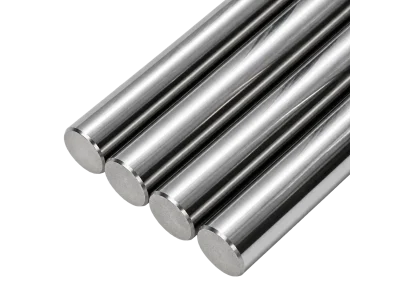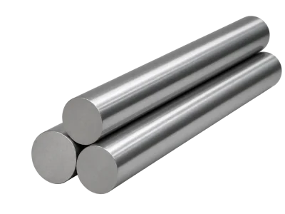
Rough-Ground Solid Rods
Rough-ground solid rods with the diameter allowance stated for each size.
View Details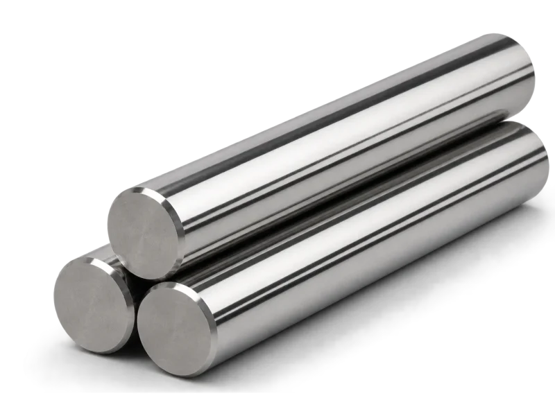
Ground rods combining an end chamfer and side-lock slot. Check slot location, width and depth against your holder drawing.
Ground rods combining an end chamfer and side-lock slot. Check slot location, width and depth against your holder drawing.
For tool designs or holders requiring a side-lock feature. Compatibility depends on matching the slot geometry to the holder interface.
For this configuration, review the supplied outside diameter, length, surface condition and any prepared end or shank feature. Where a blank is intended for further grinding, distinguish the supplied blank diameter from the final tool diameter. Positive allowance is not a finished-diameter tolerance.
The 2026 KENIN catalog provides the following specification fields for this product:
Ground diameter D (h5/h6 as listed), length L, slot width L1, distance from end to slot center L0, slot depth h, dimensional tolerance and slot angle θ. Catalog table lists 9 configurations with D from 6 to 20 mm and θ 45°; verify each row against the source table.
Do not transfer a dimension or tolerance from another product family. Where the catalog lists multiple configurations under the same nominal diameter, select the exact row matching the required hole, pitch, length or profile.
★ Standard stock · ● Made to order. These are catalog supply classifications, not live inventory. Confirm availability and lead time with your quotation. Original units and tolerance notation are retained.
| No. | D (h5/h6) | L (mm) | Slot width L1 | End to slot center L0 | Slot depth h | Tolerance | θ (°) |
|---|---|---|---|---|---|---|---|
| 1 | 6 | 50 | 4.2 | 15.9 | 4.8 | -0.075,-0.0 | 45 |
| 2 | 6 | 57 | 4.2 | 18.0 | 5.1 | -0.075,-0.0 | 45 |
| 3 | 8 | 63 | 5.5 | 18.0 | 6.9 | -0.090,-0.0 | 45 |
| 4 | 10 | 72 | 7.0 | 20.0 | 8.5 | -0.090,-0.0 | 45 |
| 5 | 12 | 83 | 8.0 | 22.5 | 10.4 | -0.110,-0.0 | 45 |
| 6 | 14 | 83 | 8.0 | 22.5 | 12.7 | -0.110,-0.0 | 45 |
| 7 | 16 | 92 | 10.0 | 24.0 | 14.2 | -0.110,-0.0 | 45 |
| 8 | 18 | 92 | 10.0 | 24.0 | 16.2 | -0.110,-0.0 | 45 |
| 9 | 20 | 104 | 11.0 | 25.0 | 18.2 | -0.130,-0.0 | 45 |
| Diameter (mm) | Tolerance (mm) |
|---|---|
| All | ISO h6/h5 |
Select the grade for the intended tool, workpiece material and cutting operation. KENIN reviews grade suitability and availability for the requested rod geometry; grade names do not establish equivalence.
For tool designs or holders requiring a side-lock feature. Compatibility depends on matching the slot geometry to the holder interface.
This page describes the blank configuration, not a guaranteed finished-tool performance result. Final tool life and machining performance depend on tool geometry, coating, machine conditions, workpiece and cutting parameters.
For requirements outside the listed catalog configuration, send a dimensioned drawing. Depending on the geometry and confirmed manufacturing scope, the review may cover:
Non-standard requests are subject to technical review and manufacturing feasibility confirmation.
Provide holder/tool drawing, D, L, slot width/depth/location, angle, chamfer, tolerance, grade and quantity.
Please also include:
Also state the required supply condition, surface requirements, desired delivery date and inspection method or acceptance specification. Delivery and feasibility are confirmed with the quotation.
Rough-ground solid rods with the diameter allowance stated for each size.
View DetailsMetric ground rods supplied in listed fixed lengths with a specified end chamfer.
View DetailsSolid cylindrical blanks with positive diameter allowances for subsequent grinding.
View DetailsSend KENIN the product reference, dimensions, tolerance requirements, grade or application details and quantity. A dimensioned drawing helps the team review the exact configuration.