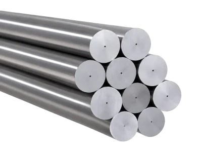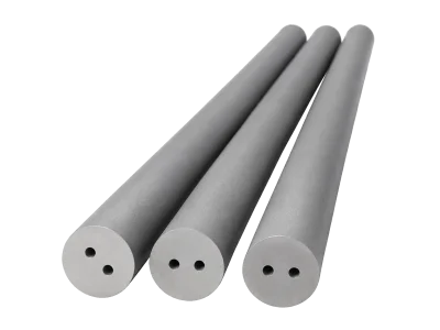
Twin Straight Coolant-Hole Rods
A carbide rod blank with two parallel straight coolant passages arranged symmetrically or to the specified cross-section.
View Details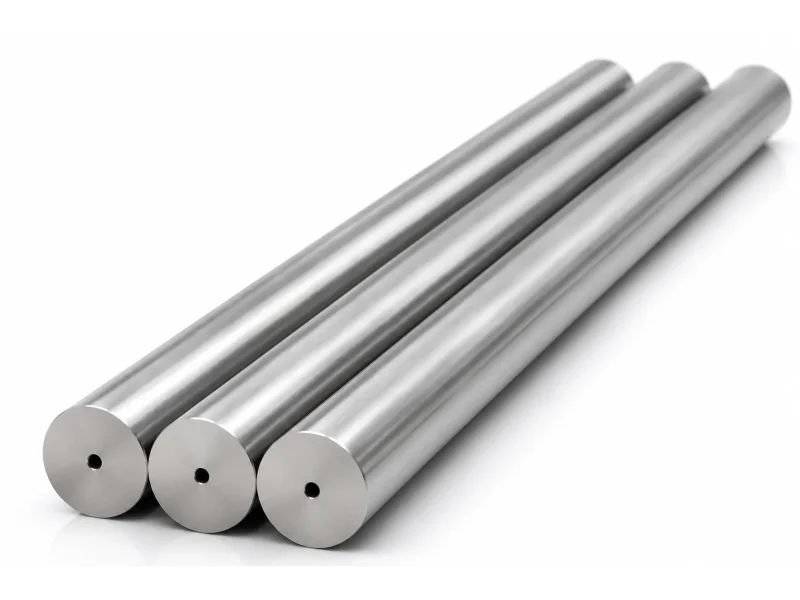
A cemented carbide rod blank with one axial coolant passage running along the rod length.
A cemented carbide rod blank with one axial coolant passage running along the rod length.
For drill and other tool blanks designed around a single internal coolant passage. Hole position and diameter must match the final tool geometry.
For this configuration, the coolant-hole geometry is a functional part of the blank design. Confirm the hole count, hole diameter d, hole tolerance, hole center position, eccentricity es and TK where two holes are present. The cross-section must match the tool drawing.
The 2026 KENIN catalog provides the following specification fields for this product:
Blank D, D tolerance, L, coolant-hole diameter d, hole tolerance and eccentricity/offset es. Selected examples include D 2.2–16.2 mm; this is not the full listed range, with lengths of 300, 330, 360 or 415 mm depending on row; refer to the full table for exact combinations.
Do not transfer a dimension or tolerance from another product family. Where the catalog lists multiple configurations under the same nominal diameter, select the exact row matching the required hole, pitch, length or profile.
★ Standard stock · ● Made to order. These are catalog supply classifications, not live inventory. Confirm availability and lead time with your quotation. Original units and tolerance notation are retained.
| Blank D | D tol. | L (mm) | Hole d | d tol. | Offset es | Stock |
|---|---|---|---|---|---|---|
| 2.2 | +0.1~+0.3 | 300 | 0.3 | ±0.10 | 0.10 | ★ |
| 3.2 | +0.1~+0.3 | 300 | 0.4 | ±0.10 | 0.10 | ★ |
| 4.2 | +0.1~+0.3 | 330 | 0.6 | ±0.10 | 0.10 | ★ |
| 5.2 | +0.1~+0.3 | 330 | 0.8 | ±0.10 | 0.15 | ★ |
| 6.2 | +0.1~+0.3 | 330/360 | 1.0 | ±0.15 | 0.15 | ★ |
| 6.2 | +0.1~+0.3 | 330/360 | 1.3 | ±0.15 | 0.15 | ★ |
| 7.2 | +0.1~+0.3 | 330/360 | 1.0 | ±0.15 | 0.15 | ★ |
| 8.2 | +0.1~+0.4 | 330/360 | 1.0 | ±0.15 | 0.15 | ★ |
| 8.2 | +0.1~+0.4 | 330/360 | 1.3 | ±0.15 | 0.15 | ★ |
| 9.2 | +0.1~+0.4 | 330/360 | 2.0 | ±0.20 | 0.15 | ★ |
| 10.2 | +0.1~+0.4 | 330/360/415 | 1.5 | ±0.15 | 0.15 | ★ |
| 10.2 | +0.1~+0.4 | 330/360/415 | 2.0 | ±0.20 | 0.15 | ★ |
| 11.2 | +0.1~+0.4 | 330/360/415 | 2.0 | ±0.20 | 0.15 | ★ |
| 12.2 | +0.1~+0.4 | 330/360/415 | 2.0 | ±0.20 | 0.15 | ★ |
| 12.2 | +0.1~+0.4 | 330/360/415 | 3.0 | ±0.20 | 0.15 | ★ |
| 13.2 | +0.2~+0.5 | 330/360/415 | 2.0 | ±0.20 | 0.15 | ★ |
| 14.2 | +0.2~+0.5 | 330/360/415 | 2.0 | ±0.20 | 0.20 | ★ |
| 15.2 | +0.2~+0.5 | 330/360/415 | 2.0 | ±0.20 | 0.20 | ★ |
| 16.2 | +0.2~+0.6 | 330/360/415 | 2.0 | ±0.20 | 0.20 | ★ |
| 16.2 | +0.2~+0.6 | 330/360/415 | 3.0 | ±0.20 | 0.20 | ★ |
| 17.2 | +0.2~+0.6 | 330/360/415 | 3.0 | ±0.20 | 0.20 | ★ |
| 18.2 | +0.2~+0.6 | 330/360/415 | 3.0 | ±0.20 | 0.20 | ★ |
| 19.2 | +0.2~+0.6 | 330/360/415 | 3.0 | ±0.20 | 0.20 | ★ |
| 20.2 | +0.3~+0.8 | 330/360/415 | 2.0 | ±0.20 | 0.20 | ★ |
| 20.2 | +0.3~+0.8 | 330/360/415 | 3.0 | ±0.20 | 0.20 | ★ |
| 21.2 | +0.3~+0.8 | 330/360/415 | 3.0 | ±0.20 | 0.20 | ★ |
| 22.2 | +0.3~+0.8 | 330/360/415 | 3.0 | ±0.20 | 0.20 | ★ |
| 23.2 | +0.3~+0.8 | 330/360/415 | 3.0 | ±0.20 | 0.20 | ★ |
| 24.2 | +0.3~+0.8 | 330/360/415 | 3.0 | ±0.20 | 0.20 | ★ |
| 25.2 | +0.3~+0.8 | 330/360/415 | 3.0 | ±0.20 | 0.20 | ★ |
| 26.2 | +0.3~+0.8 | 330 | 3.0 | ±0.20 | 0.25 | ★ |
| 27.2 | +0.3~+0.8 | 330 | 3.0 | ±0.20 | 0.25 | ★ |
| 28.2 | +0.3~+0.8 | 330 | 4.0 | ±0.25 | 0.25 | ★ |
| 29.2 | +0.3~+0.8 | 330 | 4.0 | ±0.25 | 0.25 | ★ |
| 30.2 | +0.3~+0.8 | 330 | 5.0 | ±0.25 | 0.25 | ★ |
| 31.2 | +0.3~+0.8 | 330 | 5.0 | ±0.25 | 0.25 | ★ |
| 32.2 | +0.3~+0.8 | 330 | 5.0 | ±0.25 | 0.25 | ★ |
| Length L (mm) | Tolerance (mm) |
|---|---|
| <150 | +0.5/+1.0 |
| 150≤L≤300 | +1.0/+2.0 |
| >300 | +2.0/+5.0 |
Select the grade for the intended tool, workpiece material and cutting operation. KENIN reviews grade suitability and availability for the requested rod geometry; grade names do not establish equivalence.
For drill and other tool blanks designed around a single internal coolant passage. Hole position and diameter must match the final tool geometry.
This page describes the blank configuration, not a guaranteed finished-tool performance result. Final tool life and machining performance depend on tool geometry, coating, machine conditions, workpiece and cutting parameters.
For requirements outside the listed catalog configuration, send a dimensioned drawing. Depending on the geometry and confirmed manufacturing scope, the review may cover:
Non-standard requests are subject to technical review and manufacturing feasibility confirmation.
Provide D, L, hole diameter d, eccentricity, tolerances, grade/application and quantity.
Please also include:
Also state the required supply condition, surface requirements, desired delivery date and inspection method or acceptance specification. Delivery and feasibility are confirmed with the quotation.
A carbide rod blank with two parallel straight coolant passages arranged symmetrically or to the specified cross-section.
View DetailsTwin straight coolant passages with reduced hole diameters for designs that require a different internal-channel layout from the standard twin-hole series.
View DetailsSend KENIN the product reference, dimensions, tolerance requirements, grade or application details and quantity. A dimensioned drawing helps the team review the exact configuration.