A tungsten carbide wear part can resist abrasion for a long time and still fail through a small edge chip or a sudden crack. When that happens, ordering the same component in a harder grade is not necessarily the right response. The investigation needs to consider the material, geometry, manufacturing history, installation and operating conditions together.
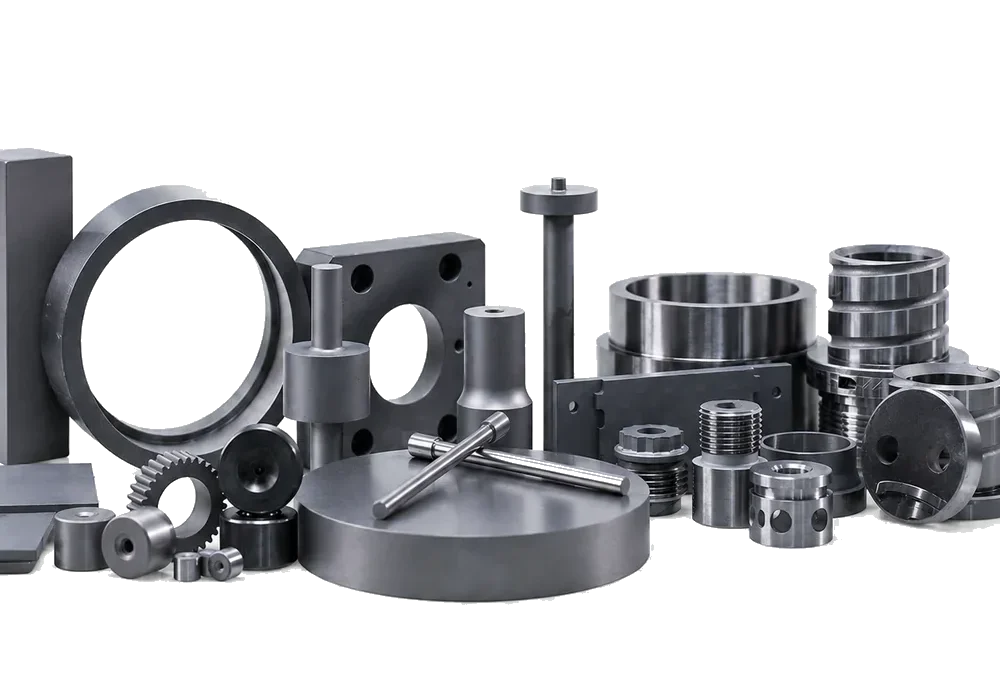
This guide helps engineers and industrial buyers organize a failure review for carbide bushings, sleeves, valve seats, nozzles, die inserts and other wear components. The observations below are starting points for investigation, not diagnoses from appearance alone.
Hardness Does Not Mean Immunity to Fracture
Cemented tungsten carbide combines hard carbide grains with a metallic binder. Hardness describes resistance to indentation; it does not tell the whole story about resistance to cracking. A material suitable for steady abrasion can behave differently under impact, bending or concentrated loading.
Fracture toughness concerns resistance to crack propagation. Transverse rupture strength (TRS) describes bending strength under specified test conditions and is not a direct substitute for fracture toughness or an impact rating. When comparing data, confirm the test method and the application rather than ranking grades by one number.
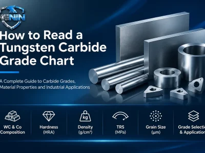
Use the KENIN tungsten carbide grade database as a preliminary comparison tool. Values marked pending confirmation remain subject to technical documentation review; a grade designation alone does not establish a guaranteed composition or a suitable replacement material.
Start With When and Where the Damage Appeared
Separate damage observed on receipt, after finishing, during assembly, at startup and after extended service. Keep the drawing revision, batch identification and installation history with the failed part. A useful investigation compares damaged and undamaged components from the same assembly or production batch.
| Observation | Questions to investigate | Evidence to collect |
|---|---|---|
| Chip at an exposed edge | Was there handling damage, foreign-particle impact, edge loading or inadequate support? | Edge detail, assembly position, contact marks and handling history |
| Crack noticed after installation | Were the fit, alignment, seating surfaces and installation method checked? | Measured mating dimensions, assembly sequence and fixture details |
| Damage after heating or cooling | Did temperatures, coolant delivery or the mounting condition change? | Operating sequence, temperature history and joining records |
| Damage near a finished surface | Could finishing defects or residual stress be involved? | Grinding or electrical discharge machining records and surface examination |
| Rough surface with material loss | Is the mechanism abrasion, erosion, binder corrosion or a combination? | Fluid chemistry, deposits, wear location and comparison with unused material |
A crack found after assembly may have started earlier. Likewise, visible surface wear does not rule out an installation problem. Record the sequence before selecting a corrective action.
Impact, Geometry and Support
Impact can create localized loading that a wear-resistant component was not designed to accommodate. Review foreign particles, intermittent contact, vibration and changes in machine alignment. Pay particular attention to unsupported edges, thin sections and abrupt changes in geometry.
A tougher grade may be worth evaluating, but it should not become a substitute for correcting an unsuitable support or contact arrangement. EVERLOY identifies both impact and the required fracture toughness as considerations when assessing carbide cracking. See its technical explanation of carbide cracking.
For a drawing review, mark the damaged location and indicate the direction of loading. Identify whether that area is a sealing face, a guiding surface, a working edge or a nonfunctional corner. Any proposed radius or chamfer must remain compatible with the part’s function.
Installation Stress and Thermal Mismatch
For fitted carbide bushings or sleeves, the carbide and surrounding housing must be considered as an assembly. Verify the specified fit against measured dimensions, check seating and alignment, and document how installation loads were applied. There is no universal interference value appropriate for every diameter, wall thickness, grade and housing.
Carbide and steel expand differently with temperature. A fitted assembly therefore needs review over its intended operating range, not only at inspection temperature. Changes in service temperature can alter the loading within the assembly.
Brazed carbide assemblies introduce another thermal history. Differential contraction during cooling can leave stress in the carbide, and damage may become apparent during brazing or later processing. Joint design, filler selection and the heating and cooling procedure need to be assessed together. Johnson Matthey’s brazing guidance discusses cracking of cemented tungsten carbide joined to steel.
Finishing Damage and Thermal Cycling
Review how the component was ground, polished or electrically discharge machined before attributing an early failure to its grade. Surface integrity can matter as much as dimensional acceptance. A part meeting its size requirement may still need investigation for localized processing damage.
Electrical discharge machining (EDM) uses localized electrical discharge energy. Its settings and finishing sequence can affect the resulting surface, including the risk of microcracks. CB-CERATIZIT describes this issue in its carbide machining technical newsletter. Its process examples are not universal machining instructions for every carbide grade or machine.
Also document changes between startup, steady running and shutdown. An interrupted coolant supply or a changed heating cycle is useful investigation evidence. Process-specific examination is needed to distinguish a manufacturing defect from damage introduced later in service.
Binder Corrosion Can Contribute to Surface Breakdown
In some chemically aggressive environments, corrosion removes binder from the carbide surface. This can leave carbide grains less effectively supported and accelerate material loss. Hyperion explains this mechanism in its cemented carbide corrosion guidance.
A roughened surface alone does not prove corrosion. Record the working fluid, concentration, temperature, cleaning chemicals and exposure history. If chemical attack is suspected, ask for an appropriate material and surface examination. Do not assume that increasing hardness or changing to a nickel-containing binder automatically resolves every corrosion problem.
What to Send for a Technical Review
A concise evidence package is more useful than an instruction to supply a stronger grade. Include:
- The drawing revision, part number, material designation and available material inspection records.
- Overall photographs and close-ups with a scale, showing the damaged location and its orientation in the assembly.
- Service hours or cycles, the number of affected parts and whether failures are isolated or repeat at the same location.
- The working medium, abrasive particles, temperature changes, mechanical loading and operating sequence.
- Mating-part dimensions and materials, installation method, support arrangement and any recent maintenance changes.
- Finishing or joining records and an unused comparison part, where available.
Preserve the failed surfaces and fragments for examination; avoid regrinding or polishing away potential evidence before the investigation. Follow the equipment owner’s procedures for taking a damaged component out of service, especially where pressure containment or rotating equipment is involved.
Validate the Correction Before a Larger Order
Agree what the trial should demonstrate: reduced chipping, retained dimensions, acceptable leakage, stable fit or another application-specific criterion. Record the proposed material or design change and the conditions under which it is tested. Where practical, avoid changing several unrelated variables without documenting them.
For a broader material comparison, read how to choose a carbide grade for wear applications. For nozzle-specific symptoms, see the tungsten carbide nozzle guide. Neither a hardness match nor a similar grade name establishes equivalence between suppliers.
Frequently Asked Questions
Does a chipped carbide part prove that the grade is defective?
No. Material quality is one possible part of the investigation, alongside geometry, manufacturing, handling, assembly and service conditions. Establish the failure mechanism before assigning a cause.
Should I choose a harder grade to prevent cracking?
Not automatically. Hardness and resistance to cracking describe different properties. Evaluate the loading and support conditions, then compare appropriate material options with the supplier.
Can the cause be confirmed from a photograph?
Photographs help locate damage and plan the investigation. Confirmation may require the physical part, inspection records and suitable examination of the material and fracture surface.
Can a cracked wear part be repaired and reused?
Do not assume that removing a visible chip makes a part serviceable. Repair feasibility and acceptance criteria require a component-specific assessment by the responsible technical team.
Discuss Your Carbide Wear-Part Application With KENIN
KENIN supplies custom tungsten carbide wear parts based on drawings and application requirements. Send the drawing, damage photographs, current material information, service conditions and required quantity so our team can review the request and discuss an appropriate next step.
Contact KENIN Carbide for an application review and quotation.